The content of this post was provided by friend Jack K. of South Bend Indiana. He scanned this article from part of his massive library of AIST/AISE yearbooks. He has many duplicates which he has offered me and I hope to acquire those soon. Thanks Jack!
ACME Steel might be called the company that grew from a staple. In 1880, a furniture dealer, M. E. McMaster, aggravated by packing damage to his shipments, began to experiment with hoop steel. He devised a staple with barbs on each end which held bed rails safely during shipment and effectively pre-vented damage. He patented his staple, designed a machine for its manufacture and found a ready market for the new product in packaging and crating.
By 1900, the company had become the Acme Flexible Clasp Co. and eventually entered the steel strapping field. Later, it also expanded into the manufacture of strapping tools.
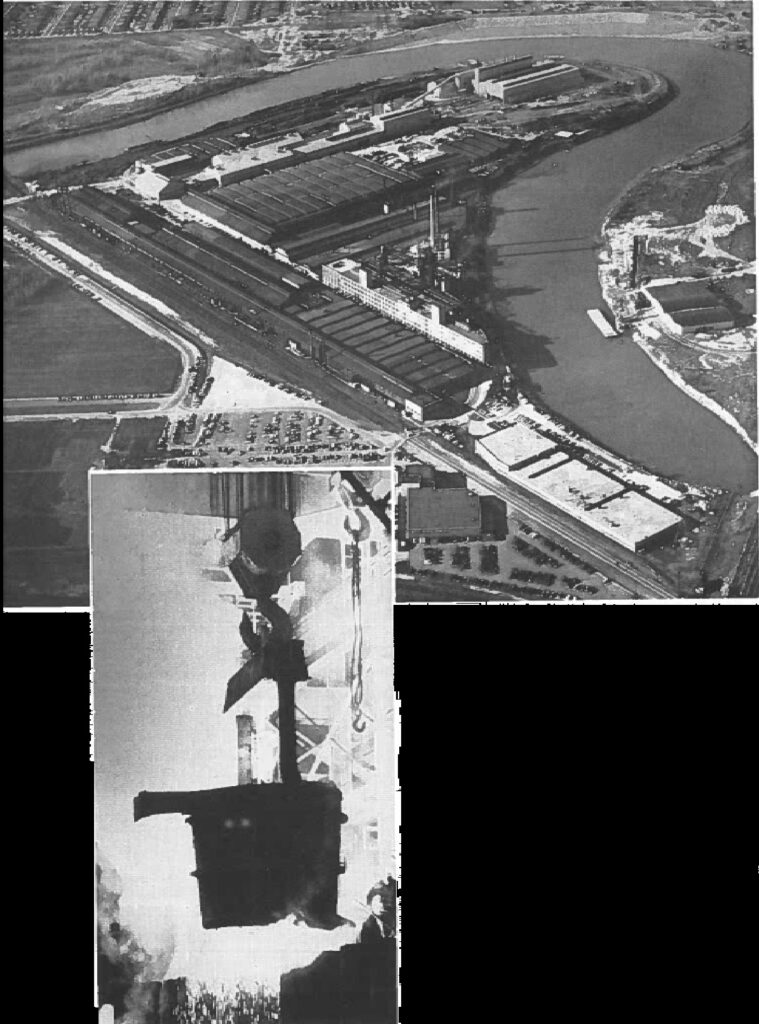
By 1917, it became clear that facilities for rolling steel strip were essential. In 1919, a continuous hot mill went into operation, rolling purchased billets into strip. This was built on a new site at Riverdale, Ill., on the Little Calumet River, about 16 miles south of downtown Chicago.
Through the years, the company and the Riverdale plant has expanded, adding more hot mills, cold mills and finishing equipment to meet the growing demand for hot and cold rolled strip.
Acme Steel Co.’s main plant is still at Riverdale, where the company has continued to convert purchased billets and slabs into hot rolled and cold rolled carbon steel strip. It also manufactures steel strapping, strapping tools, flat stitching and wire stitching machines, steel hoops, slotted angles and other specialty products.
Finding its dependence on outside steel sources frequently placed it in a precarious position from the standpoint of availability and price, Acme made its first step toward integration by acquiring Newport Steel Corp. at Newport, Ky., in 1956. This wholly owned, semi-integrated subsidiary is now operated as the Acme-Newport Steel Co., and has a steel capacity of 600,000 tons of ingots per year.
More recently, Acme has built steelmaking facilities at Riverdale, and with the pioneering spirit so often found in small companies, selected a new combination of operations to form a unique steelmaking process, the first of its kind in the Western hemisphere. The new facilities are based on continuous hot blast cupolas which supply molten metal to top-blown basic oxygen furnaces. The project also includes soaking pits, a blooming mill and a billet mill. The plant was designed to produce 450,000 tons of ingots per year with provisions for future expansion to over 700,000 tons. Cost of the initial step was $35,000,000.
Raw materials for steelmaking consist of iron and steel scrap, pig iron, coke, limestone, fluorspar, burnt lime and roll scale. They arrive by rail, barge or truck. Metallics are unloaded by crane in the scrap aisle into storage or weighing bins at 15,000 tons capacity.
Nonferrous materials are dumped into a track hopper and moved by belt conveyor to overhead storage bins. Bin capacity for coke, limestone and fluorspar for the cupolas is 3000 tons. Bins for limestone, fluorspar, burnt lime and mill scale for the converters total 1800 tons capacity. inside bin capacity holds materials for eight to ten days’ operation. The handling system is designed to unload material for 1.5 days of operation in 8 hr.
Additional ground and pit storage is available in the plant yard, where the various materials are stocked and reclaimed by locomotive crane.
Principal material requirements for initial operations run about as follows (tons/month):
- Cupolas (7 days per week, 3 shifts per day)
- Pig iron 15,000
- Steel scrap 22,500
- Coke 7,500
- Limestone 2,000
- Fluorspar 200
- Converters (7 days per week, 2 shifts per day)
- Hot Metal 35,700
- Steel scrap 6,400
- Burnt lime 2.000
- Ferro manganese 200
- Ferro silicon 100
This is predicated on 37,600 tons of ingots per month, resulting in 32,000 tons of slabs and billets.
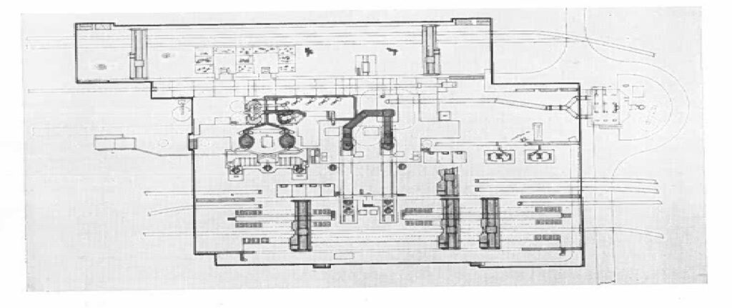
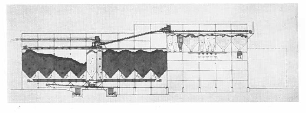
The new melt shop consists of five adjacent aisles running 450 to 480 ft in length. The scrap aisle is 80 ft wide and is served by two 10-ton cranes. Next is the stock bin aisle, 28 ft wide, followed by the 80 ft cupola-converter aisle with eight cranes of various types, from 5-ton hoists for oxygen lances to 20-ton cranes for cupola charging. The hot metal aisle, with two 100-ton cranes, is 80 ft wide, and the pouring aisle, with one 100-ton crane and two 35-ton stripper cranes, is 80 ft wide.
Metallics for the cupola charge are handled by magnet-equipped cranes which deposit the material into two 240-cu ft batch weigh hoppers. These hoppers dump into 360-cu ft charging buckets which are carried on transfer cars into the cupola-converter aisle. Coke, limestone and fluorspar are put into a 125-cu ft weigh hopper, from which the desired amounts are drawn into a motorized batch weigh lorry by means of vibrating feeders. The lorry in turn loads the drop-bottom charging buckets. Two 20-ton overhead cranes, one for each cupola, lift the loaded buckets and move them over the top of the cupolas. As a bucket is lowered onto a gas lock at the top of the cupola, a cover seals the top of the bucket. The doors at the bottom of the lock then open, allowing the charge to drop into the cupola. Thus, top pressure can be maintained as high as 12-in. water column and the escape of gas and dust is prevented.
The cupolas operate with a stock column about 40 ft, high above the tuyeres. Stock level is controlled by a radioactive isotope stock line indicator. Charging equipment is designed to charge 12,000 lb of metallics with the required amount of coke, limestone and fluorspar once every 6.8 minutes to each cupola.
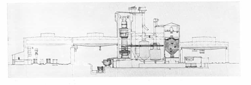
CUPOLAS
Molten metal for the steelmaking process comes from two continuous hot-blast cupolas 66 ft-8 in. high from bottom to the top of the water seal. The cupolas are placed on 48-ft centers and space is provided for a third unit: The shells of the cupolas are made of 2-in. plate for the base and 1 1/2 in. plate for the base, body and stack. Shell diameters are 13 ft-3 1/2 in. at the bottom, tapers in to 11 ft above the tuyeres, and to 10 ft at the top.
The cupolas are externally water-cooled in the melting zone and stack by five water spray rings. Thus, no lining is required in these sections. The only refractories in the cupolas are bottoms made up of 4 1/2 in. of fire-brick topped with 11 1/2 in. of rammed basic material, and carbon block walls 9 to 22 1/2 in. thick extending from the base plate up past the tuyeres.
Each carbon lining consists of 88 carbon blocks, laid four courses high. The blocks in the bottom course are 35 in. high, those in the other courses are 24 in. high. Block thickness decreases from bottom to top, giving a uniform inside diameter of 9 ft-6 in.
Each cupola is equipped with 12 water-cooled cast copper tuyeres seated in coolers. The tuyeres are 3 1/2 to 5 in. in diameter, located about 8 ft above the base plate. The tuyeres extend 18 in. inside the inner face of the carbon lining and are angled five degrees down from the horizontal. A 30-in. inside diameter bustle pipe brings blast to the tuyeres.
Gas offtakes are located about 52 ft above the bottom plate. Just above the offtakes are water-cooled doors, which, with a water sealed cap, prevents gas leakage from the cupola top.
Cupola charges vary considerably, depending upon conditions. A typical charge might be 52 per cent. steel scrap and 48 per cent pig iron and cast iron scrap, with 16 per cent coke, 5 per cent limestone and 1/2 per cent fluorspar. Cupola yield ranges above 90 per cent.
The cupolas are blown by four positive displacement, motor-driven blowers. Three blowers are rated at 14,700 cfm each, with 600-hp motors, one at 7700 cfm with a 300-hp motor. Their design pressure is 7.25 psi but operation up to 8.33 psi is possible. The blowers exhaust into a common blast main designed with valving for automatically controlled split-wind blowing. Blast for each cupola normally runs about 12,000 cfm.
Gases leave the top of the cupola at about 250 F. They contain about 4 grains of solids per cu ft. These gases are thoroughly cleaned in a combination mechanical-electrical scrubbing unit composed of a dust catcher, cyclone whirler and washer tower, and an electrical precipitator of wet pipe type, with 200 eight-in. tubes. The clean gas is moved by a booster to a combustion chamber where the gas is burned. About one-half of the products of combustion are vented to the atmosphere, while one-half passes to the blast preheater.
This is a metallic-tube heat exchanger designed to heat 40,000 cfm of air to 1200 F. Automatic control keeps the air temperature within five degrees of the desired temperature. The exchanger can also use natural gas if desired.
Water from the tower washer is put through a thickener 85 ft in diameter x 20 ft deep, designed to clarify 4500 gpm of water. Effluent from the thickener contains only 40 to 80 ppm of solids. Sludge is put through a vacuum type drum filter.
Each cupola can melt from 25 to 50 tons per hr, depending on the operating practice. A charge consisting principally of steel scrap holds down production. Maximum production is attained with a charge of pig iron and cast iron scrap, with foundry coke. The cupolas can be run with either basic or acid slag practice, as desired, giving flexibility of operation.
The cupolas are intended to operate continuously except for minor delays for repairs to iron spouts, slag separators, etc. Molten metal runs constantly into two 200-ton mixers placed in front of the cupolas. The mixers are gas-fired to maintain metal temperatures.
Slag from the cupolas is granulated at the skimmers and sluiced into a nearby pit. Slag volume runs about 185 lb per ton of metal.
Iron analyses from the cupolas will vary somewhat with the make-up of the charge. For a charge as pre-viously given, the iron will contain approximately 3.7 per cent carbon, 0.6 to 0.7 per cent manganese, 0.2 to 0.3 per cent silicon, 0.08 to 0.12 per cent phosphorus and 0.04 to 0.045 per cent sulphur.
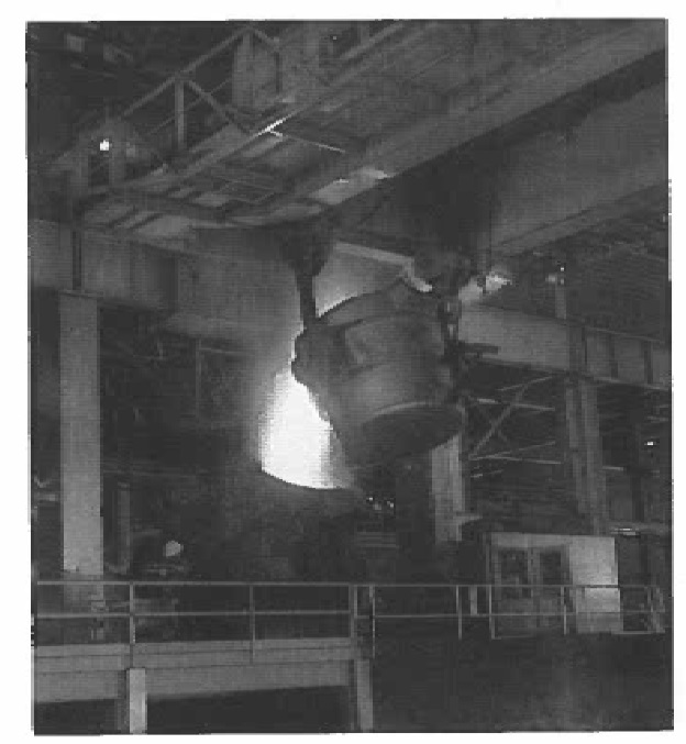
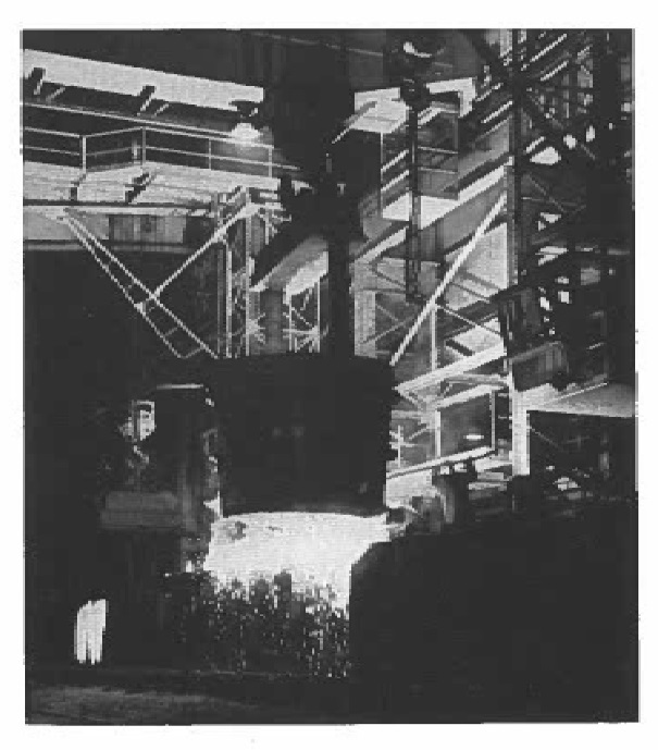
Iron is poured from the mixers into 75-ton hot metal ladles, which are moved by a 100-ton crane to the converters.
CONVERTERS
There are two identical 50/60-ton oxygen steel converters, located on 48-ft centers, with provisions for a third unit. The converter shells are 14 ft-6 in. in-side diameter and 25 ft high with a dished bottom and an eccentric conical top section with a renewable tap hole section in the long side. The center section is made of 2-in. plate, the top and bottom sections of 1 1/2-in. plate. The three sections are welded together under specifications for unfired pressure vessels. The top section carries a steel flange to which is bolted a renewable cast steel nose ring. The nose opening is 4 ft-6 in. in diameter inside the lining and is inclined 17 degrees from the horizontal. The opening is offset toward the scrap-charging and slagging side of the vessel.
Around the center section of each shell is a box-type trunnion ring built up of 1 1/2 in. web plate with top and bottom flanges 5 in. thick. Forged steel trunnions, welded into the ring on each side, ride in bronze-bushed bearings 27 in. in diameter, supported on stand of welded steel plate 2, 2 1/2 and 3 in. thick. Height from the base of the stand to the trunnion centerline is about 9 ft. All trunnions are water cooled.
The shell is lined with 273 1/2 in. of tar dolomite, 4 1/2. in. of magnesite brick, 4 in. of rammed basic material and 18 in. of rammed tar-dolomite brick. The bottom consists of 12 in. of magnesite brick and 21 in. of rammed tar-dolomite.
Each vessel is tilted by two 200-hp mill type motors with full magnetic reversing, plugging, armature shunt time-current controllers. These motors work through conventional reduction units, a special worm gear reducer and a 6-in. circular pitch cast tooth shrouded herringbone gear on one trunnion. The drive is capable of rotating the vessel through 360 degrees twice in one minute. Converter elevation is such that the vessel can be turned upside down with a ladle beneath.
A typical charge to a vessel for a 60-ton heat consists of approximately 120,000 lb of molten iron from the cupolas and 16,000 lb of cold steel scrap, with three to five per cent burned lime and perhaps fluorspar to the extent of two lb per ton of metal.
Scrap is brought from the scrap aisle in long, open-end boxes on a transfer car which accommodates two boxes. The box is lifted by a 10-ton double hoist crane and tilted over the converter mouth so the scrap slides into the vessel. Iron is poured into the vessel from the 75-ton ladles.
Fluxes and miscellaneous materials are drawn from overhead bins in the bin aisle into a monorail carrier which transports the materials and dumps them into the converter.
When the converter is charged, the oxygen lance is lowered by a 5-ton hoist to within four to six ft above the bath surface and the blow is begun. The lance is 43 ft long, and seamless tubing with a copper tip. A central tube within the lance conducts oxygen. Around this tube are two other concentric tubes which form a water passage to and from the tip.
Each converter is provided with a spare oxygen lance which is always hooked up to the oxygen and cooling water supplies, ready for service.
Oxygen pressure is maintained at 175 psi in the supply line. Oxygen flow during the blow may be varied between 3000 and 4000 cfm. Oxygen consump-tion runs about 1800 cu ft per ton of steel. The total heat time is about one hour, tap-to-tap, with about 30 min actual blowing time.
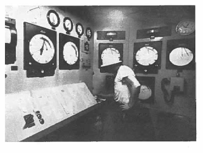
Each converter is equipped with an automatic control system which regulates and totalizes the flow of oxygen to the converter. It will meter a given amount of oxygen to the vessel and then automatically stop the flow when this amount has been used.
The complete control system also regulates lance movement, lance cooling, converter tilting, ladle transfer car and dust collecting system. The various elements are so interlocked as to prevent operations when some element is out of sequence.
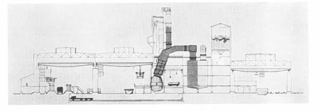
Fumes and dust blown out of the converter nose is collected by a water-cooled hood and led through a brick-lined duct to a collecting system. The gases first pass through a cooling tower 23 ft x 26 ft-6 M. x 40 ft high, fabricated of %-in. steel plate. The inlet side of the tower is lined with 3 1/2 in. of gunned refractory. Water sprays in the tower reduce the temperature of the gases from about 1500 F to approximately 250 F.
From the tower, the gases flow through a 90 in., flue 230 ft long to a dry-type electrostatic precipitator. Steam jet blowers along the flue prevent dust accumulations. The precipitator is 54 x 30 x 60 ft high and contains 69,000 sq ft of plate area.
The converter collecting system operates under induced draft from a fan rated at 200,000 cfm, 6-in. water column at 250 F. The cleaning efficiency is guaranteed at 99.5 per cent.
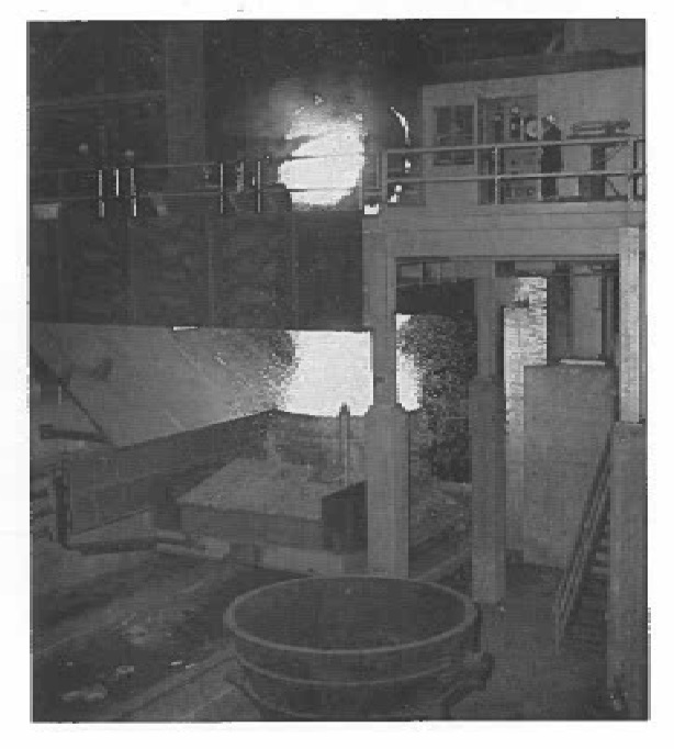
When the blow is finished, the slag is poured off into a thimble and the steel then poured into a 75-ton ladle, both of which rest on a motor-driven transfer car running beneath the converter. The car is then moved across the hot metal aisle into the pouring aisle. Yields from the converter process average about 87 per cent.
A pouring platform is provided on the full length of each side of the pouring aisle. Stools are placed on the ground for the full length of both platforms, each stool accommodating four ingot. molds. This provides enough molds so that each one is normally used once every 12 hours.
Serving the pouring aisle are two 35-ton traveling stripper cranes and, between them, a 100-ton ladle crane. Steel produced ranges from low carbon rimmed grades to high carbon killed grades. Three mold types are
used: 21 1/4 x 23 1/4-in. and 25 1/2 x 27 1/2-in. big-end-down open tops, and 2412 x big-end-down hot tops. The open top molds are 82 in. high, and by vary-ing pouring heights from 62 to 78 in., ingot weights of 9870 to 12,270 lb are attained. The hot topped molds are 7414 or 831 in. high, giving gross weights of 8770 and 11,300 lb.
Approximately 80 per cent of the steel produced goes into big-end-down, open top molds, and only 20 per cent into hot topped molds.
A platform for the preparation of hot tops is located in a lean-to at the side of the pouring aisle. This plat-form is served by small cars which carry hot tops across the pouring platform from the preparation lean-to.
A laboratory located near the converter serves these units and the cupolas. It contains a direct-reading spectrometer, sample preparation equipment and facilities for conventional carbon and sulphur determinations.
OXYGEN PLANT
Oxygen of 99.5 per cent or higher purity is provided from a plant located near the melt shop. This plant furnishes 116 tons of oxygen per day which is produced by low temperature fractional distillation of air. This is a four-step process consisting of compression, cooling, liquefaction and distillation of air into oxygen and nitrogen.
The gaseous oxygen is stored in a 240,000-cu ft bank of 37 high pressure cylinders 80 ft long. The melt shop draws on this bank through a pressure reducing station which supplies oxygen at 200 psi. A portion of the oxygen is diverted as liquid to a storage tank which has a capacity of 3,000,000 cu ft gaseous equivalent. This liquid can be vaporized and used as required during routine maintenance shutdowns of the oxygen plant. Total storage amounts to enough oxygen to keep the steel plant operating for about 50 hours.
BLOOMING MILL
After the ingots are stripped, they are put into two refractory-lined transfer cars which are then moved to the soaking pits or to an ingot storage area.
There are 12 soaking pits arranged in three blocks of four pits each forming a single row in line with the mill. Each pit is 20 ft long x 8 ft wide x 13 ft-6 in. and is fired by one combination burner which will handle natural gas or fuel oil, located in the top of one end wall. Maximum fuel input is 20,000,000 Btu per hr.
Combustion air, furnished by one 16,000-cfm fan for each block, is not preheated, but provisions were made for future installation of recuperators when desired. Each battery is served by a 150-ft stack, 5 ft inside diameter.
Each pit is designed to heat a charge of 23 ingots 1:About 55 tons total) from cold to 2350 F in 10 to 11 hr. Estimated fuel consumption, without recuperation, is about 1,200,000 Btu per ton.
Each pit is equipped with automatic controls for pit temperature, fuel-air ratio and pit pressure, Fuel flow is recorded and totalized. Instruments and controls for each battery are grouped in a modern enclosed control house.
When ready for rolling, ingots are drawn from the pits by a 15-ton fixed-tong pit crane and carried to the mill in a tilting-pot, front-discharge buggy. An auxiliary 10-ton hanging-tong pit crane is also provided.
The approach table and entry table extend for about 131 ft to the mill stand.
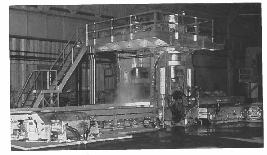
The blooming mill is a 35-in. two-high reversing unit, with cast alloy steel rolls of 35-in. collar diameter and 80 7/8 in. body length running in composition bearings. The rolls carry pass grooves of 3 1/16, 3 3/4, 7 1/2, and 12 in., 33 3/16 in. bullhead. The top roll is balanced by a counterweight, and is moved up and down by 12-in. mill screws of 1 1/2 in pitch. The screwdown mechanism is driven by two 75-hp mill type motors operated under magnetic control. Roll lift speed is 204 in. per min and the maximum opening is 30 1/4 in. at the bullhead. Housing posts have a 400-sq in. sectional area.
The mill is driven by a 6500-hp, 0/60/140 rpm, 700-volt d-c motor working through herringbone pinions of 35-in. pitch diameter, 50-in. face. This motor draws power from a motor-generator set consisting of two 3000-kw, 700-volt d-c generators, a 137,000-lb steel plate flywheel 180 in. in diameter, and a 4500-hp, 360-rpm, 12,000-volt induction motor. The drive provides a normal operating torque of 400,000 ft-lb and a maximum torque of 1,138,000 ft-lb.
In the mill, the ingot is handled by side guard manipulators, with a finger lift for turning on the entry side. The manipulators are driven through rack and pinion by four 35-hp mill type motors. The lift finger is operated by a 50-hp mill type motor. These motors are provided with magnetic control. Mill scale is sluiced to a scale pit.
The main drive motor and its motor-generator set, controls and switchgear are located in a motor-room approximately 158 ft long x 69 ft wide. The rotating units are cooled by forced air, with the air being drawn into the basement, passed through a filtering system, and blown up through the machines. Two air compressors are also located in the motor room.
Leaving the mill, steel passes over a succession of tables to a shear 187 ft from the mill. This shear is operated through a clutch by a 250-hp, 900-rpm a-c motor under magnetic control. The shear is capable of cutting sections of hot steel up to 80 sq in. Crops are chuted to a pit below the shear and later removed by magnet crane and placed in railroad cars.
A closed-circuit television camera is installed at the shear so the operator can see the back ends of the steel, enabling him to adjust cuts to attain maximum yield.
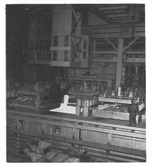
After shearing, slabs are removed from the table and transported over a hot bed about 70 ft long to an ad-jacent slab yard.
From the shear, blooms may also proceed straight ahead over tables to the billet mill.
The blooming mill normally receives ingots 21 1/4 x 23 1/4 in., 8520 lb or 25 1/2 x 27 1/2 in. 12,270 lb. At speeds up to 1200 fpm, it reduces these to slabs ranging from 8 x 3 in. to 22 1/4 x 2 1/2 in. or to blooms of 6 x 6 in. to 9 1/4 x 6 in. Product is about equally divided between slabs and blooms. The mill rolls at rates of 60 to 120 tons per hr, depending on the size of product delivered.
BILLET MILL
In line with the blooming mill and about 100 ft beyond the hot bed is the first stand of the billet mill. This mill has the following characteristics:
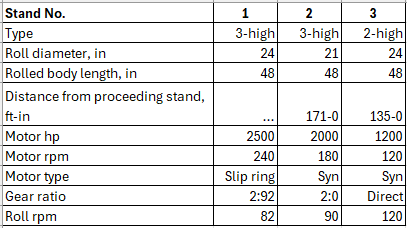
Roll necks run in composition bearings. Pinions are of 26-in. face, 24 and 21-in. pitch diameters. Roll ad-justments are made by manually operated screws, 4 in. in diameter, 1%-in. pitch. Pinions and reduction gears are lubricated by a central circulating oil system.
The three-high stands are not equipped with tilting tables. Instead, on their down-mill sides, sloping pieces of specially shaped channels rest on the upper pass level. As the steel moves down-mill through the lower pass level, it moves under the hinged channels. When the table rolls bring the steel back, it moves up the channels into the upper pass level. As the steel leaves the upper pass level on the up-mill side, it drops to the mill table.
The billet mill receives 6 x 6-in. or 9 1/4 x 6-in. blooms, 30 to 33 ft long, and reduces them to squares 1 3/4 to 2 1/4 in. or slabs up to 8 5/16 x 2 1/8 in. Billets are rolled with five passes in the first stand and three or five passes in the second stand, depending on finished size. Slabs are usually given three passes in the first stand, three in the second stand and one in the third stand.
Leaving the last stand of the mill, the steel passes over a table provided with three swing-frame 42-in. hot saws to two chain-type cooling beds 60 ft long x 30 ft wide. From the discharge ends of the beds, a roller table approximately 270 ft long connects back into the slab yard.
Extra stands are provided which can be set up for roll changes and then substituted for the working stands when the change is to be made, thereby reducing down-time.
An inspection and scarfing area in the slab yard serves both the blooming mill and the billet mill. Following this procedure, slabs and billets are bundled, banded and sent to the stock yards of the hot strip mills.
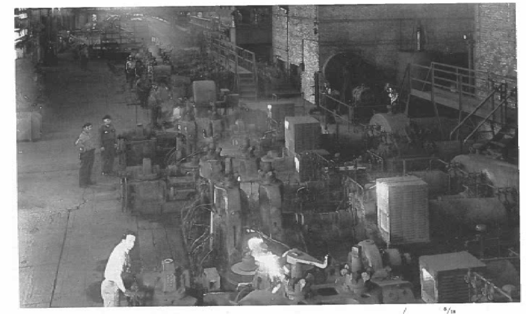
HOT STRIP MILLS
Prior to the installation of the steelmaking facilities and blooming mill, production at Riverdale centered chiefly on three hot strip mills with a total capacity of 590,000 tons of hot rolled strip per year.
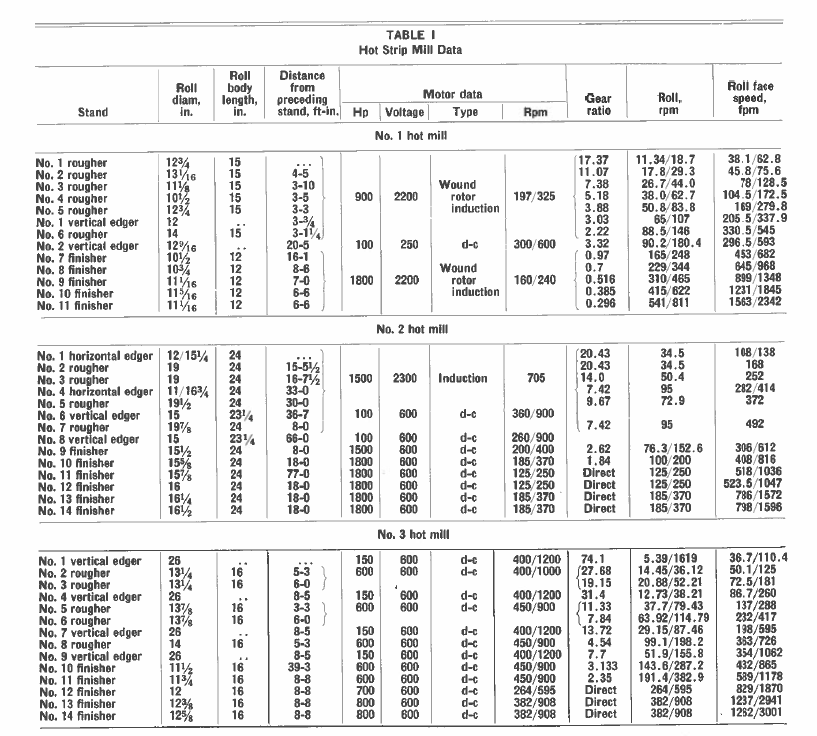
Details of these mills are given in Table I and in the following:
No. 1 mill – Put into operation in 1919. 13 stands. Uses billets 1 5/8 in. square or up to 2 1/8 x 3 1/4 in., 27 to 29 ft long. Produces strip 0.025 to 0.05 in. thick in widths of 2 to 3 15/16 in., at average rate of 17 tons per hr. All product is coiled.
One heating furnace, single zone continuous, re-cuperative hearth 25 x 31 ft. Natural gas or producer gas. Production, 23 tons per hr.
Rougher and finisher roll necks run in composition bearings, edger rolls in babbitted bearing.
Main drive induction motors arranged in Scherbius systems for variable speed. The 900-hp rougher drive is regulated by a motor-generator set consisting of one 70-kva, 133-volt generator and a 230-hp, 2200-volt induction motor.
Regulation for the 1800-hp finisher drive comes from a 270-kva, 205-volt generator driven by a 335-hp, 2200-volt induction motor.
Mill discharges through water-cooled trough and vibrator and over variable speed apron conveyor to vertical coilers. A muffle conveyor provides controlled cooling of coils.
Mill rated at 122,000 tons per vr.
No. 2. mill – Put into operation in 1926. 14 stands. Uses billets 3 to 22 1/8 in. wide, 2 1/2 to 3 in. thick, 10 ft long. Produces strip 3 to 11 in. wide in No. 16 gage, 3 to 17 in. wide in No. 14 gage, and 3 to 22 in. wide in heavier gages, at average rate of 41 tons per hr. About 70 per cent of the product is coiled, 30 per cent flat.
Three heating furnaces, continuous, recuperative, hearth 41 ft-3 in. x 12 ft. Natural gas or oil. 21 tons per hr each.
Finisher roll necks run in composition bearings, edger rolls in babbitted bearings; roughers, some babbitted, some composition.
Finishing stands driven at adjustable speeds by d-c motors under adjustable voltage control, using two motor-generator sets, each consisting of two 1000-kw , 600.-volt d-c generators and a 2850-hp, 2300-volt, 900-rpm synchronous motor.
Mill discharges over runout table under variable frequency control either to double hot bed about 250 ft long or to horizontal hot coiler. Cold run on each side of hot bed contains shear and horizontal coiler.
Mill rated at 288,000 tons per year.
(As this is being published, No. 2 hot strip mill is being replaced by a new 36-in. mill consisting of a two-high reversing roughing stand and a continuous train of four-high finishing stands. The new mill will produce strip up to 31 in. wide in coils weighing up to 450 lb per in. of width.)
No. 3 mill – Put into operation in 1929. 14 stands. Uses billets 1 5/8 to 8 5/16 in. wide, 1 5/8 to 2 1/2 in. thick, 28 to 30 ft long. Produces strip 3/4 to 8 5/16 in. wide, No. 18 gage and heavier, at average rate of 26 tons per hr. Product is 80 per cent coiled, 20 per cent flat.
One heating furnace, single zone, side charge, side discharge, continuous, recuperative, hearth 33 1/2 x 33 1/2 ft. 40 tons per hr.
Rougher and finisher roll necks run in composition bearings, edger rolls in roller bearings.
Entire mill driven by direct current, with adjustable voltage control. Power provided by one motor-generator set composed of two 2000-kw, 000-volt generators, a 300-kw, 250-volt generator, a 100-kw, 250-volt gener-ator and a 250-kw, 125-volt generator, all driven at 514 rpm by a 6350-hp, 12,000-volt synchronous motor.
Mill may discharge either through pinch rolls and vibrator, over apron conveyor to vertical coilers, or over runout and hot bed to three cold run tables. Mill rated at 180,000 tons per yr.
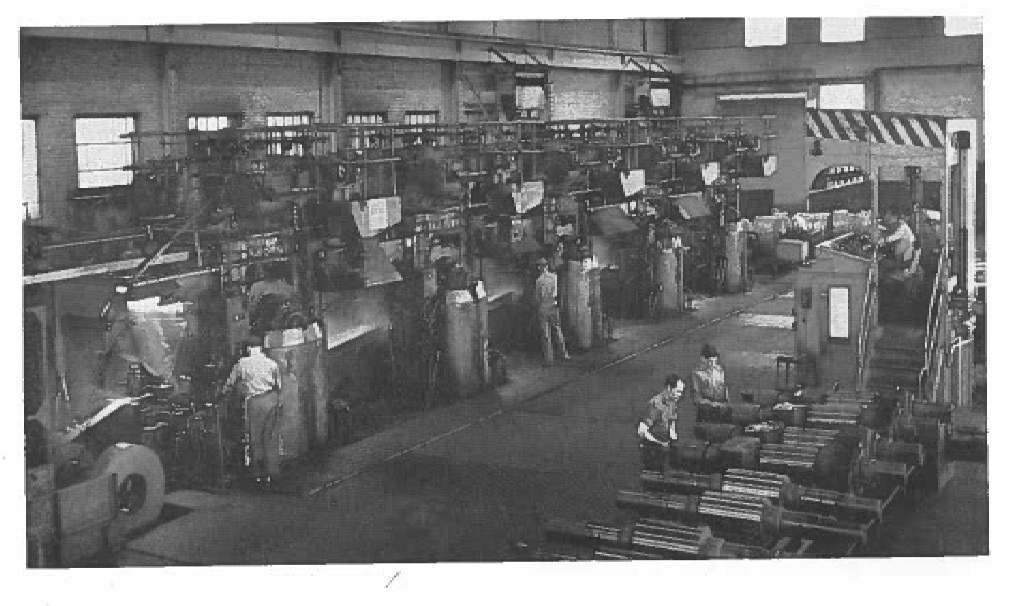
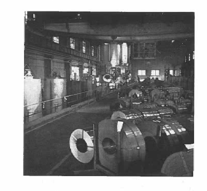
COLD ROLLING AND FINISHING
The cold mill division at Riverdale provides facilities for pickling, cold reduction, annealing, temper rolling, slitting, shearing, inspecting and packaging of strip products.
Coils received from the hot mills may be processed through three combination scale-breaking and buttweld-ing lines. These lines build up coils to a maximum of 500 lb per inch of width for further processing.
Pickling is performed on three multiple strand continuous picklers with a combined capacity of 30,000 tons per month. Each pickier has two 90-ft long acid tanks, rinsing and drying facilities and eight mandrel type toilers_ This multiple toiler system enables each line to pickle from 8 to 14 strands at any one time. Acid concentrations range between 6 and 18 per cent with the overflow piped to a batch pickier used to pickle cut-to-length material. Maximum speed of the continuous picklers is 80 fpm. Coil ends are joined together by means of steel hooks to maintain continuity.
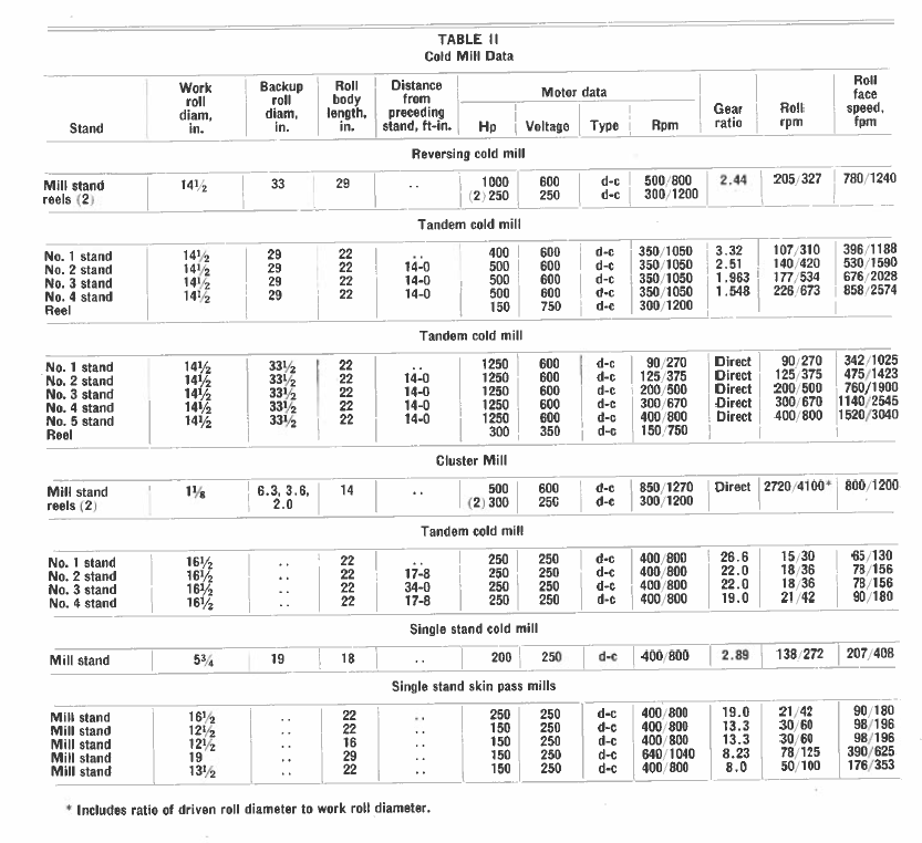
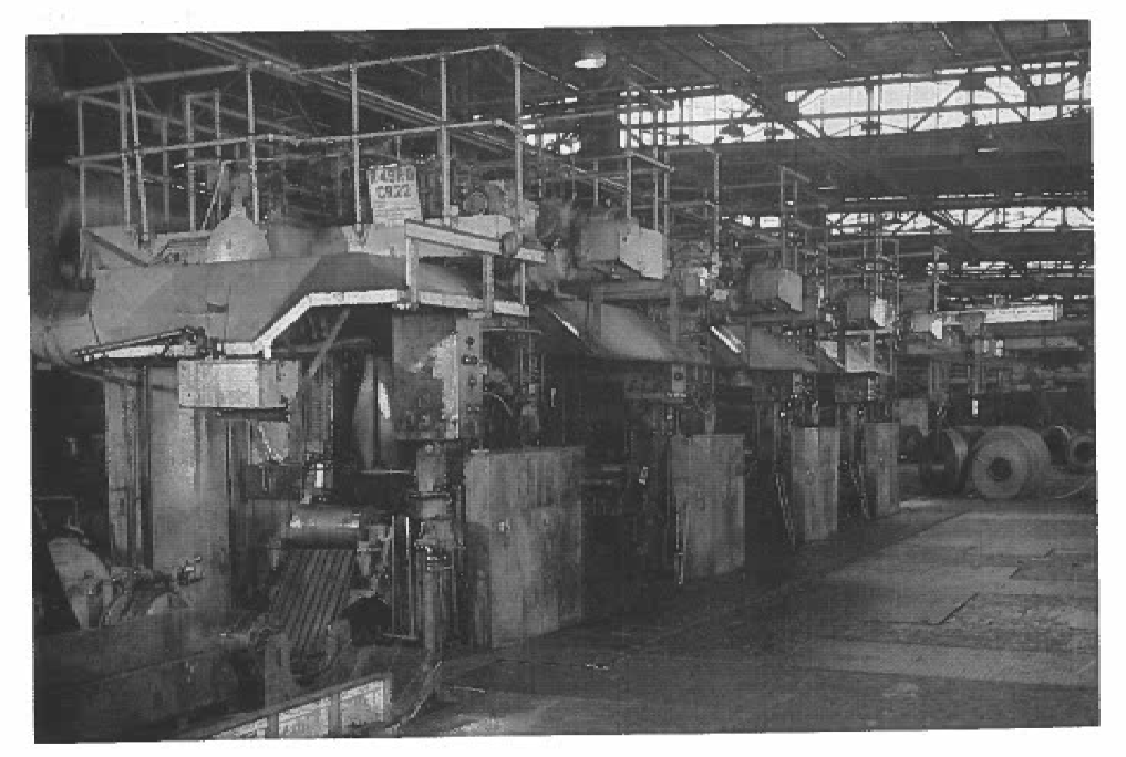
Cold reduction is performed on four 4-high mills, a. cluster mill and a 2-high mill. The 4-high mills consist of a 3000-fpm, 5-stand tandem mill: a 2500-fpm, 4-stand tandem mill, a 1500-fpm reversing mill and a 500-fpm single stand mill. The cluster mill operates at a maximum of 1200 fpm. The 5-stand mill is equipped with a noncontact gage between No. 1 and No. 2 stands which provides automatic screwdown control of No. 1 stand. The reversing mill and the cluster mill are each equipped with noncontact gages which also provide automatic screwdown control.
Temper rolling is performed on five 2-high single stand mills. In addition, the 4-stand 2-high mill is also used for temper rolling. Details of these mills are given in Table II.
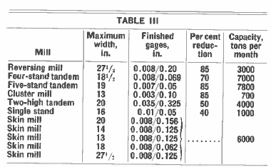
Capacity data for these mills is contained in Table III.
Coil annealing is done in 11 single stack, radiant tube, portable furnaces with 32 bases. Cut-to-length material is annealed in six stationary rectangular furnaces with removable bases and one portable removable furnace with three bases. The cut-to-length furnaces are direct fired. Protective atmosphere is supplied by four DX gas generators with a combined capacity of 14,000 cfhr and two NX gas generators with a combined capacity of 6000 cfhr. All furnaces are fired with natural gas or butane gas under automatic temperature controls. Temperatures range between 1150 and 1325 F. Total cycle time ranges between 8 to 15 hr heating, 3 to 20 hr soaking and 12 to 96 hr cooling. Monthly capacity is 7500 tons.
A normalizing furnace is used to normalize cut-to-length material as required. The over-all length of the furnace is 103 ft and the width is 9 ft. The furnace has a 33-ft heating zone, a 13-ft high-temperature cooling zone and a 33 ft low-temperature cooling zone. Material is conveyed through the furnace by means of a walking beam conveyor at speeds of two to four fpm. Capacity is five tons per hour. The furnace is direct fired and uses natural gas or butane as a fuel.
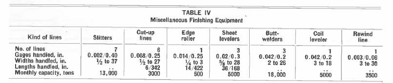
Finishing equipment also includes some miscellaneous machines as set forth in Table IV. In addition, the manufacturing departments contain 16 slitters that provide a total capacity of 15,000 tons per month.
Two hot dip galvanizing units and six electrolytic galvanizing lines provide capacity for coating 2000 tons and 8300 tons per month of the respective types.